
Optics Description
 The
XRT Mirror Assembly consists of the X-Ray Mirror Module, a thermal
baffle, a mirror collar and an electron deflector. The mirror set used
by XTR was built and calibrated for the JET-X program. The
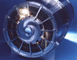
mirror module (see picture on the left) has 12 concentric gold-coated
electroformed Ni shells with focal lenght of 3500mm. In order to optimize
the angular resolution over the field of view the detector is slightly
defocused. Temperature gradients in the mirror can affect and distort
the figure and the Point Spread Function. To avoid this problem a thermal
baffle controlled by heaters balance the heat lost to space by the mirrors.
An electron deflector, consisting of a system of 12 rare earth magnets,
installed on the OBIF behind the rear face of the mirror module prevents
electrons that pass through th mirror from reaching the detector.
The
XRT Mirror Assembly consists of the X-Ray Mirror Module, a thermal
baffle, a mirror collar and an electron deflector. The mirror set used
by XTR was built and calibrated for the JET-X program. The
mirror module (see picture on the left) has 12 concentric gold-coated
electroformed Ni shells with focal lenght of 3500mm. In order to optimize
the angular resolution over the field of view the detector is slightly
defocused. Temperature gradients in the mirror can affect and distort
the figure and the Point Spread Function. To avoid this problem a thermal
baffle controlled by heaters balance the heat lost to space by the mirrors.
An electron deflector, consisting of a system of 12 rare earth magnets,
installed on the OBIF behind the rear face of the mirror module prevents
electrons that pass through th mirror from reaching the detector.
Calibration
The XRT mirros were calibrated at Panter in 1996 for
the JET-X calibration plan and again in 2000 during the XRT end-to-end
calibration. Five different energies were used in the four XRT operational
modes, both on and off-axis.
|
Source
|
C-K
|
Al-K
|
Ti-K
|
Fe-K
|
Cu-K
|
|
Energy (KeV)
|
0.28
|
1.49
|
4.51
|
6.40
|
8.05
|
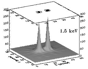
Calibration images (for two sources displaced by 20arcsec) and the measured angular resolution of the mirrors are shown in the figure.
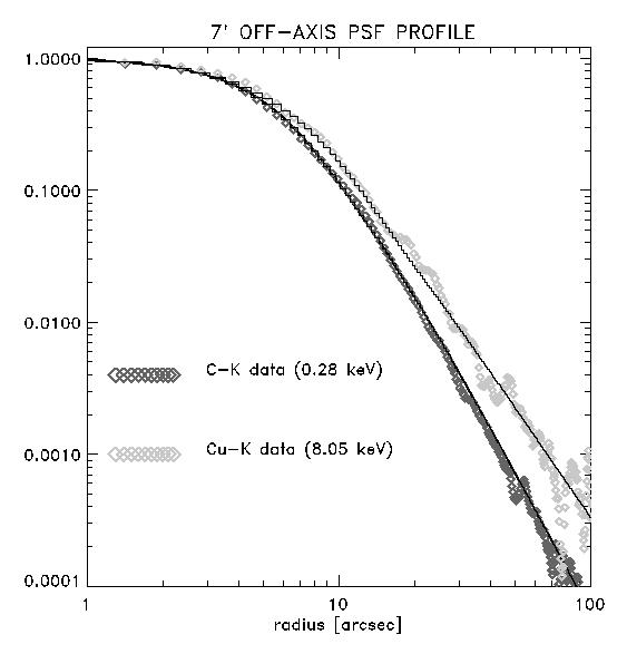
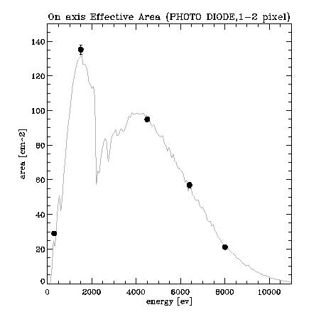
Calibration of the PSF and the effective area have been performed at Panter X-ray calibration facility. The calibration source was positioned at 130meters from the mirros. Corrections for the divergence of the X-ray beam and for pile-up effects have been applied. In the figures below the results of the effective area calibration tests in Window Timing and Photo-Diode modes are shown. The data for the PSF calbiration have been taken in imaging mode with more than 1000 counts in the image with a countrate lower than 10000counts/s. The PSF profile has fitted by a model composed by a Gaussian function for the central part of the profile and a King function for the PSF wings. An examples of PSF profile is shown in this figure. The PSF is slightly blurred on axis and better at 7arcmin off-axis due to the fact that the CCD is intentionally offset along the optical axis from the best on-axis focus. An analytical model to describe the PSF as a function of energy and angle was contructed to calculate the PSF correction for a source with a generic spectrum in a generic position of the detector. This model always described the data with a precision better than 2%. The mission requirements for the effective area, the PSF and the spatial resolution were met at the Panter Facility and through the detailed study of the PSF and the analytical model the PSF correction for astronomical sources can be calculated with great accuracy.
Swift Mission Operations Center
The Pennsylvania State University301 Science Park Road,
Building 2 Suite 332,
State College, PA 16801
USA
☎ +1 (814) 865-6834
📧 swiftods@swift.psu.edu
Swift MOC Team Leads
Mission Director: John NousekScience Operations: Jamie Kennea
Flight Operations: Mark Hilliard
UVOT: Michael Siegel
XRT: Jamie Kennea
Swift Partners
UK: UCL MSSL Univ. of LeicesterUSA: NASA/GSFC LANL Omitron SwRI
Italy: SSDC/ASI INAF OA-Brera